Announcement

Collapse
No announcement yet.

LED in Speedset... replacing LED in a board

Collapse
X
 
  • Filter
  • Time
  • Show
Clear All
new posts

    LED in Speedset... replacing LED in a board

    Anyone have any experience w/ replacing a LED built into a computer board? My LED in the speedset in 24V has gone out. Hard to watch what's happening w/o it. And my speedset is already wishy washy as it is. I talked w/ Harvey about it, he said he could get me a new unit but they don't have LED's either. Is it possible?

    Spharis? Anyone?
    Being a major OU fan and a staunch conservative.... I am perpetually vexed w/ the conundrum of who to hate more. Obama or the Univ. of Saxet.

    #2
    ****EDIT
    Crap I typed out some stuff on troubleshooting an LCD screen and replacement of those. I had you halfway to replacing an LCD screen.

    LED replacement is cake walk man. You can do it super simple with a solder sucker (the plunger style) so you don't lift any traces, and a plug in typical cheap solder iron. If you feel uneasy, buy some breadboard and a couple of board components at Radio Crack to test with a few times to get the feel of everything.

    Basically what you want to do to it to take the iron once hot (I like mine real hot for board work as the less exposure time the better) and tin the tip a bit (this helps clean it and makes it easier to melt the board joint). Have it held to where you can access both sides of the board at once and place the plunger on the BACKSIDE of the board where the LED would push through. Fully set it over the joint to maximize the plunge effect. On the front side place the iron tip near the board on the LED anode/cathode and you should be able to see when the solder pools. Once you see it pool, hit the plunger and it should completely clean the hole. Repeat on the other side.

    Once it is clean, be sure the traces didn't lift (they shouldn't) by inspecting that the rim of the board joint is kind of tinned. A lifted trace or a damaged joint will be all copper or will actually peel back from the board. Place the new LED in place making note of the anode/cathode orientation and solder it in place. Basically you heat the board and the LED together with the tip and run some solder in. The joint will wick it in by design. It's easy.

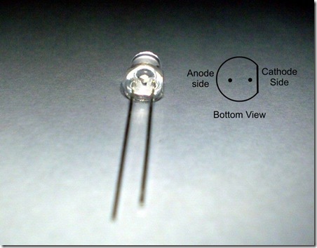
    Once more step you need to take is to figure out the anode/cathode sides on the board. The easiest way is to make note of the LED you are removing. It has a flat spot on the ring at the bottom. That side is the cathode. match the new one up. The Anode leg on the LED will usually be longer and naturally is the (+).


    If the LED you are replacing is a starburst type (digits, clocks, etc) those are even easier. Just pull the old one out after desoldering it and then install the new one correctly oriented.
    Last edited by spharis; 06-02-2008, 06:23 PM.
    http://www.wakeboatworld.com
    []) [] []V[] [])

    Comment


      #3
      BTW if you are uncomfortable and want to ship it to me, I will do it for you. Just pay the shipping both ways. PM me and I will give you my work address.
      http://www.wakeboatworld.com
      []) [] []V[] [])

      Comment


        #4
        LOL... might have to. I appreciate the info spharis. Figured you'd come to the rescue.

        I'm gonna look at it and see.
        Being a major OU fan and a staunch conservative.... I am perpetually vexed w/ the conundrum of who to hate more. Obama or the Univ. of Saxet.

        Comment

        Working...
        X