Announcement

Collapse
No announcement yet.

24Ve maximum ballast writeup...

Collapse
X
 
  • Filter
  • Time
  • Show
Clear All
new posts

    #76
    Quieting the Engine

    While I'm on the topic of that center seat support: Last fall I noticed that most of the engine noise in the passenger compartment was coming from that center seat support. It turns out that there is a open gap on either side that conducts noise straight from the engine compartment into the passenger area. In addition, the front of that center section is a single layer of fiberglass - not very acoustically isolating.

    The front of the section was deadened by the addition of a layer of engine-compartment-rated acoustic insulation ("Dynamat" is a popular brand, though this is a different product):
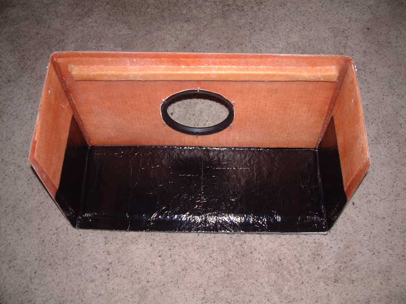


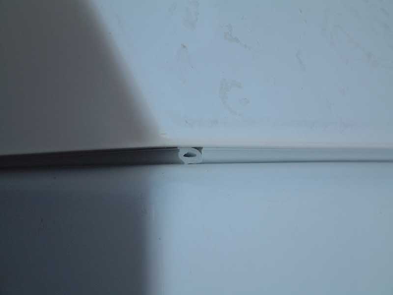
    The gap was handled by installing a strip of closed-cell adhesive backed gasketing material to both sides of the section...
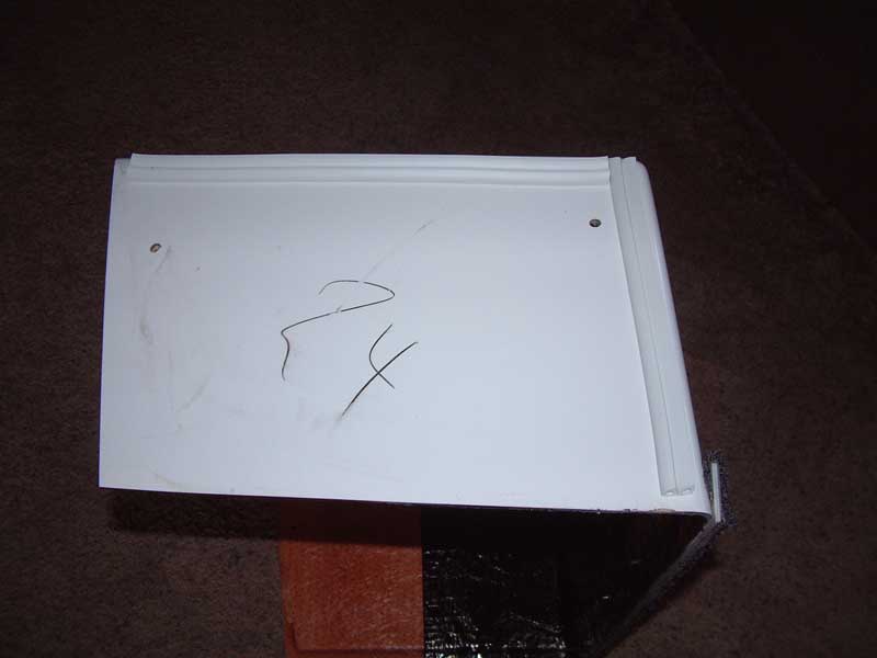


    ...that compresses when the center section is installed:


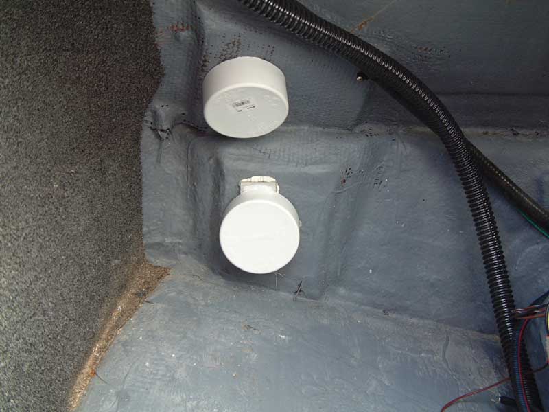
    Next up: Intake pump installation. Thanks!
    Comment


      #77
      Quick addition to protecting your sac...

      I forgot I took a photo of how the endcaps cover the transom hardware before the fat sacs were installed. Here it is, just to clarify my earlier explanation:


      A nice, inexpensive, and reversible solution to the problem.

      Comment


        #78
        Plumbing the inlet side...

        When it was time to start installing the inlet pumps and fittings, I found lots of references to people having problems with their speedometers and cruise control "right after I installed my ballast system". The theory ran that turbulence from the inlet fitting, if installed in front of the speedometer sensor, could be the cause. For that reason, I wanted to avoid disrupting the hull surface in front of the 24Ve's triducer.

        Other criteria for fill pump locations include depth below the waterline to increase the hydrostatic pressure feeding the inlet side of the pumps, and ease of access to the ball valves in case a leak occurs due to failure of a pump housing or fitting.

        I spent a lot of time researching possible locations for the fill pumps, including multiple messages and threads here on TigeOwners. The factory provided photos and engineering drawings of their install locations, which would normally be the obvious choice except for this:


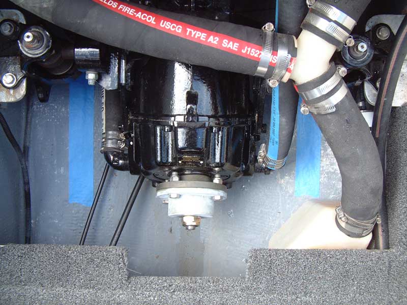
        This is a photo of the factory's normal install area. The blue tape indicates straight lines coming forward from the triducer (on the left) and the engine's raw water intake (on the right). The factory normally installs pumps in this area on both sides of the keel.

        Advantages of this area include 1) it's just about the deepest point below the waterline, which boosts hydrostatic pressure as mentioned above, and 2) it's relatively easy to access in emergencies if you leave the backing nuts off of the rearmost seat cushion (Tige installs a flush-mount hatch in the fiberglass seat support immediately above this area).

        Disadvantages of this area are obvious in the above photo. The vertically open area is very restricted, and most of it is on the starboard side which is right in front of the triducer. Yes, there are areas to the left and right of the line immediately in front of the triducer - but remember the hull slopes up here away from the keel. Turbulence coming off of a throughhull moves rearward at an angle that varies with hull speed, a problem that could be a nightmare to troubleshoot and resolve since speedo/cruise behavior would vary with boat speed.

        The safest course is to leave the entire starboard area in front of the triducer undisturbed... but that eliminates the largest hull area in the photo. (How I wish Tige would reverse the sides they choose for the triducer or raw water inlet - or mirror-image the fuel tank so it consumes space on the starboard side instead of the port!)

        That leaves the port side (right side of the photo) for throughhull and pump installation. And as you can see, things are very tight in there. The fuel tank is the major problem, as its big footprint and filler hose are right where one could otherwise install 1-2 vertically-mounted pumps.

        Another challenge came from the size of the pumps. Due to the larger-than-normal size of the aft fat sacs, I wanted to use larger-than-normal pumps. Rule makes what they call their "29" series of pumps that are rated for 1600 GPH, almost 50% greater than the commonplace 405FC pumps at 1100 GPH. Furthermore, the 29 series uses an oversized motor far beyond the increase that might be suggested by its GPH rating. But using the Rule 29B meant even more volume was necessary to mount the pumps.

        It became evident that there was no way to mount two Rule 29B's and one 405FC in the port space visible above. There is more space available under the floor, toward the bottom of the photo, but that space is severely restricted vertically. Any pump mounted under there would have to use some sort of pipe elbow and sit at an angle. And that's exactly what we chose to do.

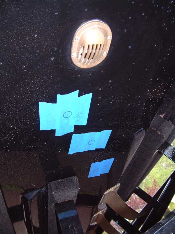
        Once the rough locations were determined, we taped off the bottom of the hull so exact holesaw locations could be marked. Usually folks measure about a dozen times to insure a match between their hole positions inside and outside the hull, but Jason at WakeMakers gave me a great suggestion: Use magnets! We found some coin-sized magnets at WalMart. This allowed my wife to move them around inside the hull, dragging the matching magnet around on the outside of the hull. Once we were certain of the locations, including no interference with trailer bunks and not being in line with each other, we marked the locations and sizes:


        The last consideration here is that one of those throughhulls will be more or less directly in front of the engine's raw water intake. While definitely not ideal, I decided this was the best compromise for the following reasons: 1) The triducer is a passive device, while the raw water intake has an impeller-style pump that actively draws a strong vacuum; 2) The raw water intake has a scoop-style throughhull that further assists the collection of water; and 3) Given 1 and 2 above, the raw water intake was less likely to suffer from any turbulence that might be generated.

        So we got to work with the hole saw. I have to say it felt a little creepy taking a hole saw to a brand new, perfectly smooth, factory perfect Tige hull.

        Properly cutting through gelcoat and fiberglass has been well documented here and elsewhere so I won't recount that material again.

        The next step was to cut backing plates for the throughhulls. Most people in the wakeboat industry don't bother with backing plates on ballast throughhulls, but seagoing vessels that use formal seacocks - already stronger than the mushroom head throughhulls used on ballast systems - virtually always use formal backing plates below the waterline. Here we're using smaller, weaker, mushroom style throughhulls so backing plates are all the more important. Furthermore, those Rule 29B pumps weigh six pounds (remember the much larger motor I mentioned?) and will be at the top of a tall stack of components, where that six pounds will have lots of leverage as the boat bounces around.

        So we have smaller, weaker throughhulls supporting heavier than normal pump motors. That translates to increased forces. Those forces will end up being transferred to the hull via the throughhulls, and such forces can contribute to spider cracking in gelcoat. Deterioration of the deck (due to tower mount points, etc.) is cosmetically undesireable but won't sink your boat. Deterioration of the hull, below the waterline, is a bit more serious!

        Backing plates were cut from 0.25 inch aluminum plate. Holes were cut in the plates to accommodate the throughhull threads, and all sharp edges and corners were broken. The throughhulls were first installed by themselves using 3M 4000UV. After several days, the flange nuts were backed off and small voids in the 3M 4000UV were carefully filled to insure 100% fill between the throughhulls and the hull itself.

        For each throughhull, a fresh ring of 3M 4000UV was run around the interior thread/hull interface. Fiber-reinforced epoxy was spread around that ring. The backing plate was lowered over the threads and smeared around a bit to get good coverage of the sealant and epoxy. Then the flange nut was reinstalled and tightened, with my wife strain-relieving the throughhull so the torque on the flange nut didn't stress the now-cured 3M 4000UV's seal with the hull. Excess epoxy that had oozed around the edges of the backing plates was cleaned up and all that remained was to let everything cure.

        (Side note: They sell a custom tool for getting a bite on those ridges within the throughhulls, but we achieved the same effect by inserting an appropriately sized open end wrench - small enough to clear the I.D. but too large to rotate past the ridges.)

        The result was 3M 4000UV providing the watertight seal for the throughhull, and fiber-reinforced epoxy providing the mechanical support for the backing plate to the hull:


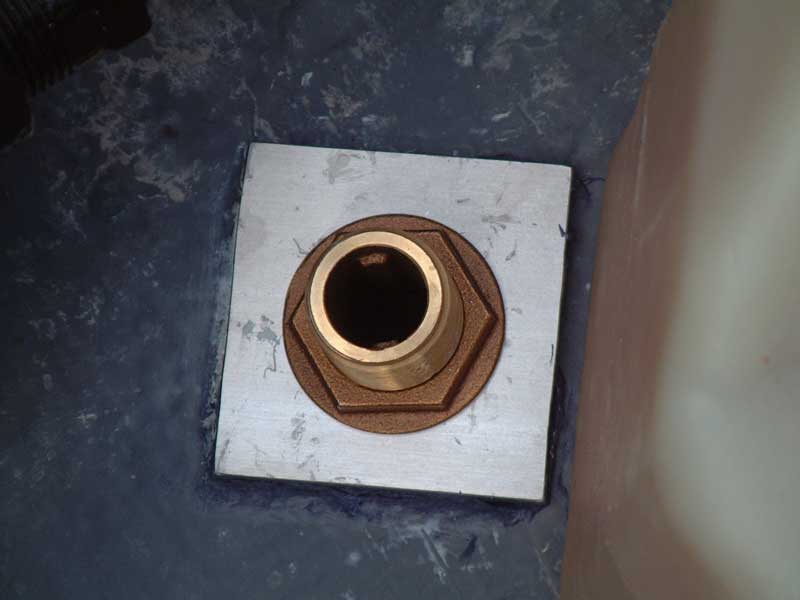
        Here are a couple of closeups, first of a one inch throughhull for a Rule 29B and then of a 3/4 inch for the 405FC that fills the bow fat sac:


        The backing plates were sized and rotated to be as large as practical without touching or risking nearby components. From there, the installation of the rear two pumps was pretty straightforward: Install the ball valve, an appropriate nipple fitting, and the pump itself.

        The frontmost pump, a 29B, presented a different challenge. It is mounted below the floor, where as noted earlier the vertical clearance is extremely limited. There isn't room for a 90 degree fitting; if turned so the pump was across the keel, the pump's outlet would be "down" and thus cause priming problems. If turned away from the keel, there isn't enough clearance to the fuel tank.

        This throughhull location worked because I located a one inch 45 degree street elbow made of red bronze. Since 45 degrees is greater than the hull angle here, it permitted the pump to be mounted across the keel while maintaining an "upward flow" from the pump's inlet to its outlet to prevent airlocks and priming problems.

        All well and good - except that now we have a six pound pump hanging at an extreme angle on bronze fittings. Not good at all. The pump must be supported somehow to take the strain off of those fittings.

        (continued in next post)
        Last edited by IDBoating; 08-30-2011, 06:24 PM.

        Comment


          #79
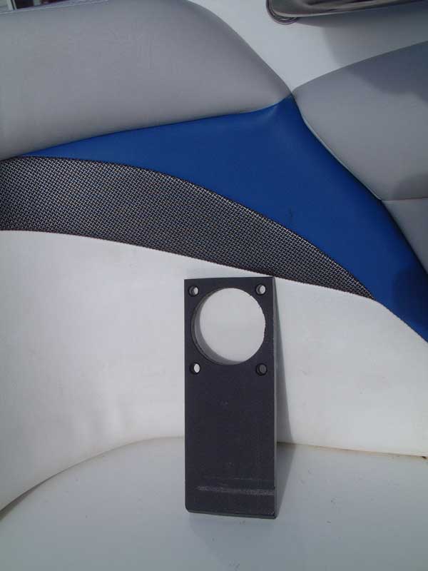
          I'd been working with Starboard for walls, dividers, etc. anyhow so it was easy to fabricate a pump support bracket:


          Look closely at the bottom edge and you'll see that it is cut at an angle to best interface with the slope of the hull's inner surface.

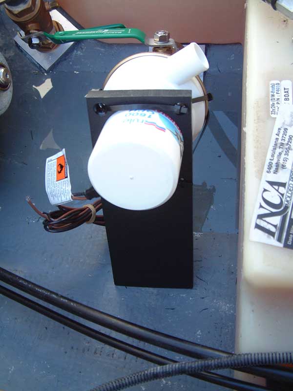
          Here's a view of the support mounted to the pump:


          ...and a side view:


          I'm currently using tyraps to hold the support in place. I may eventually switch to a pair of hose clamps around the motor body, but the tyraps seem to be doing a good job so far.

          This photo also shows the arrangement of the 45 elbow that keeps the Rule 29B's total height as low as practical. You can see that the pump crosses the keel, but given the relative angles its outlet remains above its inlet. The outlet is pointing forward to keep the outlet at the highest possible point, the better to flush air out of the system. The outlet hose loops loosely over the fuel tank and then goes back to the starboard fat sac.

          Using a "street" style 45 elbow eliminates one extra fitting. A Schedule 80 threaded "close" (i.e. shortest possible) nipple is used between the ball valve and the pump. The resulting height is just above the fuel tank and easily clears the floor when it is reinstalled, and the valve's handle is easily accessible through the underseat access port.

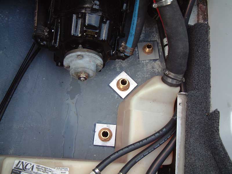
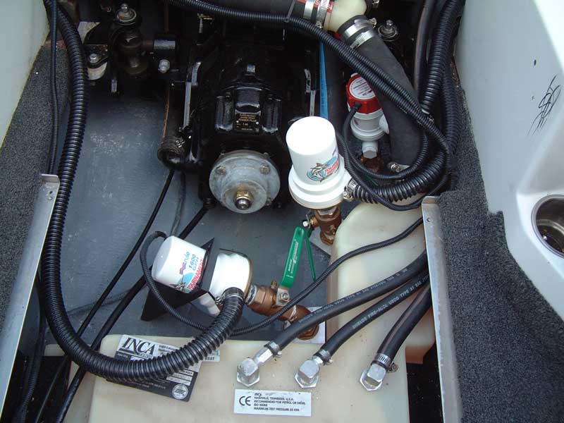
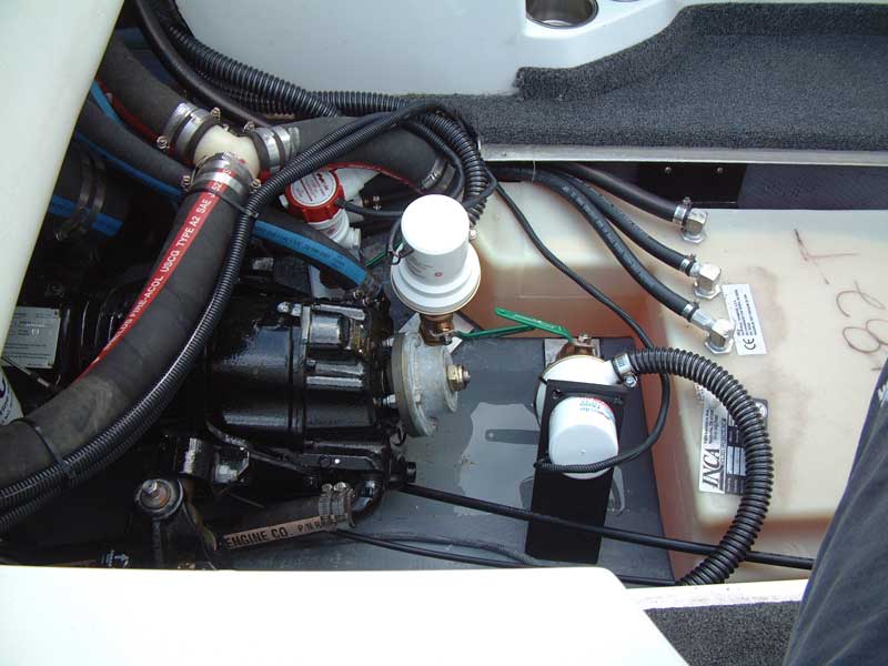
          The final, finished installation appears as follows:


          All wiring is 12 gauge stranded marine-rated wire, housed in split loom corrugated plastic tubing of appropriate size. All connections are individually tinned, soldered, and heat-shrinked before being protected in the split loom - no crimped connections here! The wiring harnesses are tyraped and routed to insure no contact with moving parts, especially that rotating bit on the front of the v-drive.

          In the first photo you can see the middle pump's mounting angle. I worried that this pump would also require some sort of mounting bracket. However, once the pump stack was complete it was so solid that I didn't feel any reinforcement was necessary.

          In the second photo you can see that the front 29B pump is turned at a slight angle. While less elegant, this provided a bit more clearance with the support ribs in the floor that gets mounted over its top.

          This installation achieved the goals of using larger, high reliability pumps for the larger fat sacs while leaving the hull in front of the triducer completely undisturbed. In an emergency, the valve handles are all accessible without tools or draining the fat sacs. And everything can be reached for inspection or service in a matter of minutes.

          More soon... thanks!
          Last edited by IDBoating; 08-30-2011, 06:37 PM.

          Comment


            #80
            I almost used those pumps. Great install, it's very clean.
            Build thread: http://www.tigeowners.com/forum/showthread.php?14787-Duffy-s-2005-24v-wakesurfing-mod-thread&highlight=duffys+24v

            Comment


              #81
              Originally posted by duffymahoney View Post
              I almost used those pumps. Great install, it's very clean.
              Thanks! We'll have to get together sometime and compare. I'm jealous of those Rule 17's you used!

              Comment


                #82
                They were a pain to install. But they work amazing.
                Build thread: http://www.tigeowners.com/forum/showthread.php?14787-Duffy-s-2005-24v-wakesurfing-mod-thread&highlight=duffys+24v

                Comment


                  #83
                  Any pics of the wave yet or are those in a different thread?

                  Comment


                    #84
                    Just a lot of video, but I'm living at the lake right now and don't have the software or hardware to transcode it to something reasonable. Plus we're enjoying an unusual bonus week of 90F+ weather after a long, cool, windy summer. I'll try to get some stills and post them.

                    Comment


                      #85
                      Pics/vids from your phone will work for now

                      Comment


                        #86
                        Photos of wave...

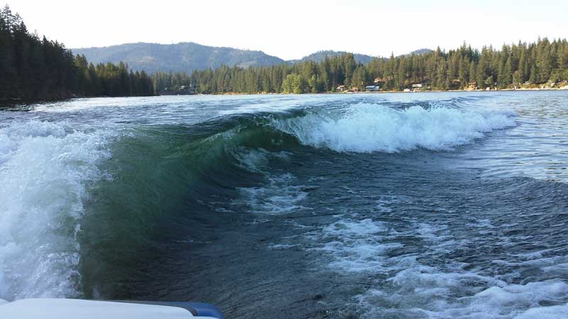
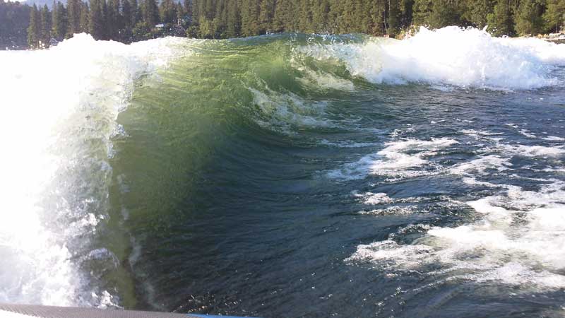
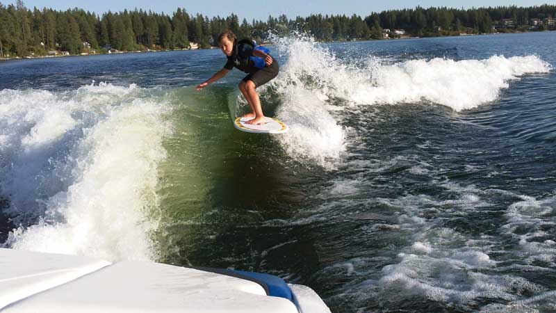
                        We took the boat out this afternoon (only the second day we've hit 100F all year!) and grabbed some photos of the wave. Conditions: Port sac ~90% full, arm deployed under seat; a few hundred pounds in the starboard sac; zero in bow sac; adult driver, adult passenger, 9YO 75 pound child, 75 pound dog in bow area, no other passengers or equipment. Speed is 10.8, TAPS is 4. Photos taken with Kodak ZX3 waterproof minicam, which is perfect for boating and which I highly recommend.

                        From the tower:


                        From the sun platform:


                        Standing in the main passenger area:


                        My 9YO carving up to the top of the wave:


                        In this setup the rub rail is still a couple of inches above the water while idling so we have more range if desired. Add a few passengers and the wave gets even bigger. We can also play with TAPS to trade some height for length. We have not yet played with adding bow ballast per RagBoy's comments, but we will soon.
                        Last edited by IDBoating; 09-09-2011, 03:37 AM.

                        Comment


                          #87
                          WOW!!! Great looking wave! Looks like an ocean wave with the nice curl on it.

                          Comment


                            #88
                            Originally posted by Timmy! View Post
                            WOW!!! Great looking wave! Looks like an ocean wave with the nice curl on it.
                            Thanks! It was a lot of work but well worth it. Maybe now folks will understand why I was asking so many detailed questions earlier in the year.

                            Thanks again for your kind comments.

                            Comment


                              #89
                              awesome. don't know how I missed this build but it's BA all the way WA'..that middle pic from the platform shows the waves' true size..quite meaty I'd say...well done.
                              my midlife crisis started at puberty and I plan on enjoying it all the way to the end..

                              Comment


                                #90
                                Great job WA!That is one serious wave.
                                I do all my own stunt work. hey ya'll watch dis.

                                Comment

                                Working...
                                X