I rarely get it when it's flat and calm and going straight.
Announcement
Collapse
No announcement yet.
24Ve maximum ballast writeup...
Collapse
X
-
 Tigé Jedi
- Jul 2010
- 4305
- TN USA
- Ballast Sensors, Hose Sensors, IMU's, Tige SpeedSet panels and more shipping every day!
I'm wondering if the drivetrain is designed to be mostly horizontal, so when we list these boats over so heavily something unexpected happens. For example, could the fluids in the transmission or v-drive slop so far to one side that they are not lubricating something properly? Engine oil pans do that sometimes if the vehicle is tilted too far - the sensor gives a false "low oil" reading or the pickup tube ends up above the fluid level.Originally posted by duffymahoney View PostI will try a 5 blade next summer. I get the same weird cavitation when heavily ballasted. Sometimes I don't get it which makes me think it could be something else.
Comment
-
we refer to that as a "bit of a list". Had a boat full of very hick fisherman try to save us the other day. They kept telling us we were listing and going to sink and that we have to balance the weight in the boat. I kept telling them it was on purpose, and they just wouldn't listen. Pretty funny.http://wake9.com/
Comment
-
 Tigé Jedi
- Jul 2010
- 4305
- TN USA
- Ballast Sensors, Hose Sensors, IMU's, Tige SpeedSet panels and more shipping every day!
Next installment: More battery shelf...
This installment provides a bit more information about the battery shelf. The battery shelf is really the key to the concept of driving the ballast weight as far low and aft as possible, so it's worth spending a bit more time on this portion of the installation.
While it is possible to move the batteries and isolator to other places, there's really no practical way to move the TAPS pump and blower. They have to be in the rear of the boat.
If you're forced to figure out something to handle those two items, why not include the batteries too? They weigh a lot, so keeping them aft is good from a ballast perspective. The 00-gauge battery cables aren't cheap (and, from an electrical perspective, should be kept as short as possible) which runs counter to the idea of moving them forward under a seat. Putting the batteries under one of the side seats also interferes with additional ballast options such as "arms" (think Enzo fat sac) and decenters their weight, which plays havoc with keeping things as symmetrical as possible to obtain good waves on both normal and goofy sides. The proper solution is to keep the batteries aft and centered.
Hence the "battery shelf". Once I figured out there was enough raw volume back there, the next step was to prototype how the various components would be best laid out. Limitations included clearance to the front of the engine and proper transfer of the battery weight to a structural member of the hull. That's why I started with a scrap piece of 1/2 inch particle board; it permitted fast and easy experimentation with component positioning, cable routing, installation and removal, etc.
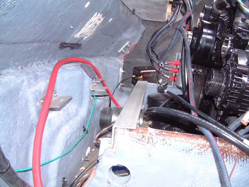
Early on I decided that the batteries would be best located on the outside edges of the shelf. This would place their weight over the engine stringers, taking care of the weight transfer issue. It would also make battery access fast and easy. However, the batteries could not be centered over the stringers since that would intrude upon the locker space I wanted to use for ballast. I felt it was unwise to rely solely on 1/2 inch Starboard to support the batteries since Starboard is not considered a structural material. Fortunately, the engine stringers do not extend all the way to the transom so it was possible to fabricate the 1.5 inch stainless steel angle support mentioned earlier.
This main support was designed to "wrap" around the top corners of the engine stringers. One stainless steel screw passed down through the each battery tray, the shelf, and the angle support to lock all three into place on top of the stringer.
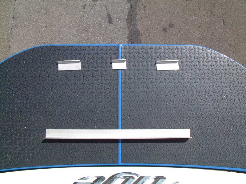
This handled the weight of the batteries. However, the other components are not without mass, so the aft edge of the shelf required anchoring as well. Hence the three angle supports mentioned previously.
Here is a shot of the battery shelf supports, on the swim deck for scale:
Here is a better shot of them installed within the hull:
With the supports in place, the prototype shelf could be installed for tweaking of shape and component placement:

Several things are worth noting here. The front edge of the shelf defines the forward-most limit for components, to insure adequate clearance to the engine. Also, the TAPS pump is oriented at an angle because its stiff output hose has a rather large minimum bend radius; the gentle routing of that hose dictated where the TAPS pump could be mounted. Just visible over the nearest battery tray is the prototype cutout for the bilge blower, which has already been moved from its originally projected location shown in pencil. Finally, notice that the placement of the battery trays relative to the ends of the engine stringers basically centers the 1.5 inch angle support beneath the batteries - nicely transferring their load to the stringers without much reliance upon the eventual Starboard material as described above.
Another detail worth mentioning here is drain water management. In several of the photos so far, you can see the undersides of the equipment storage compartments on the rear of the 24Ve. There are three little black "knobs" protruding down from those compartments. These are drains for water that may accumulate therein. In the factory configuration, those drains just empty straight down into the bilge (on top of the bilge pump, rudder assembly, muffler, etc.). However, in this installation those drains would now empty onto batteries and other components - not an ideal situation. Proper design demands that we try to anticipate and prevent problems before they occur. In this case, the solution was easy:
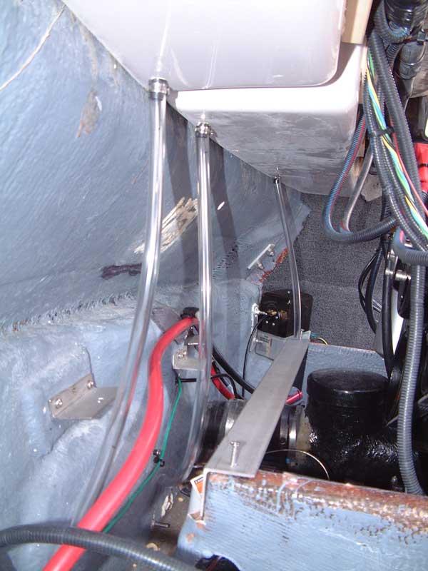
The outside diameter of the drains was measured, hose with the same inside diameter obtained, and stainless hose clamps used to secure the hoses to the drains. Now any water draining from those compartments is routed safely past the components on the battery shelf and directly into the bilge as before.
One last detail before we move on to the next phase of the installation: Bilge pump access. As discussed with Dom earlier in this thread, it may be necessary to clean or otherwise service the bilge pump at any time - even while on the water. I did not want the shelf to prevent access to the pump. This photo shows the clear access to the pump that is available even with the shelf in place:
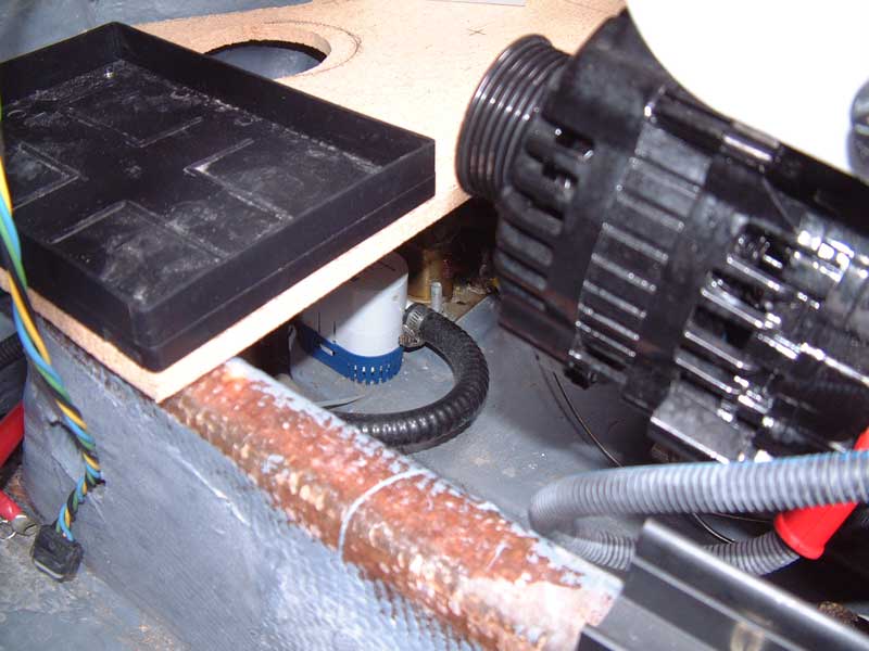
My adult hand easily passes through this space; the pump can be unsnapped from its base, its filter cleaned, and everything reassembled without removing the shelf nor anything on it. (It is also possible to reach around the end of the engine stringer if two hands are necessary, though I doubt that would ever be the case.) Access to the bilge pump is now easier than when everything was OEM.
More soon... thanks!
Comment
-
 Tigé Jedi
- Jul 2010
- 4305
- TN USA
- Ballast Sensors, Hose Sensors, IMU's, Tige SpeedSet panels and more shipping every day!
Integrated grab handle/tow eye...
Knowing that the battery isolator would no longer be in the way of an integrated grab handle / tow eye, it was possible to move forward with that mini-project. Here is the factory grab handle:
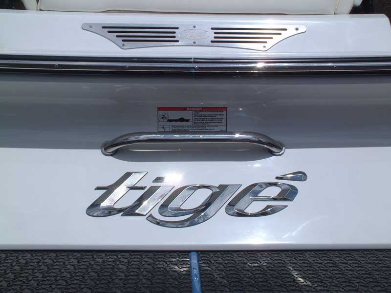
As mentioned previously, the integrated tow point required two additional holes for strain relief. Cutting those in was not difficult, but a word of warning is appropriate here: Do not presume that the bolts on such hardware are always in a straight line, or equally spaced! My integrated handle, made by the exact same fabricator as used by Tige themselves, had just enough variation that had I not measured beforehand the handle would not have covered the edges of the holes. Let the installer beware!
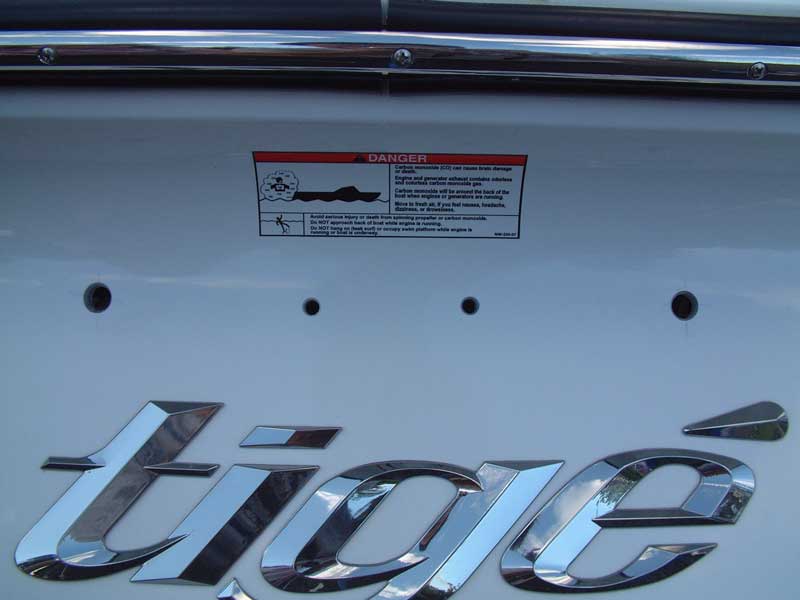
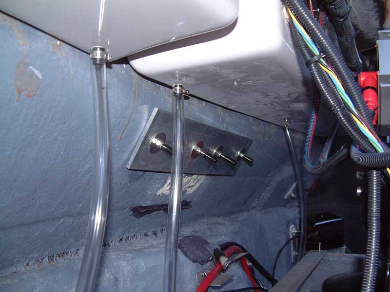
With the holes in place, the new handle could be installed. Considering that a tow ring bears enormous stress from the drag of inflatables, I cut a full-width backing plate from 1/4 inch aluminum to distribute the force across a large area of the transom. Note that the transom is not flat in this area; lacking any other preparation the backing plate would essentially only contact the transom along a thin horizontal line. To deal with this, I mounted the plate using fiber-reinforced epoxy filler. The filler was laid down in a bead along the centerline of the plate, then the plate was "smushed" into place on the transom using a figure-8 motion to spread the filler around. This approach fills the space between the flat backing plate and the curved transom, increasing the surface area into which the tow ring transfers its stress. Here is the result, with some bolt protectors on the ends of the handle bolts:
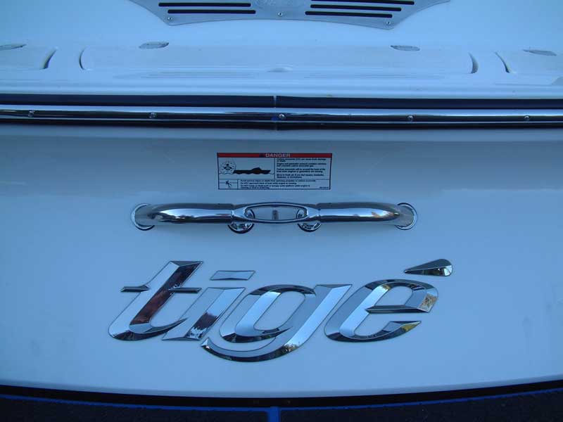
Finally, the finished product. The outermost holes are the same as with the original handle, and everything fits nicely.
Back to the ballast install in the next segment... thanks!
Comment
-
 Tigé Jedi
- Jul 2010
- 4305
- TN USA
- Ballast Sensors, Hose Sensors, IMU's, Tige SpeedSet panels and more shipping every day!
Rear locker preparation...
Having figured out where, and how, to move the batteries, TAPS pump, etc. it is time to maximize the volume for the rear fat sacs - and, importantly, drive them as deep and aft as possible. Lots of other systems just fill the existing lockers with fat sacs, but tribal lore and experience say that the 24 foot hulls need absolute maximum rear ballast far, far back to offset the leverage of that extra two feet in length. As can be seen in this thread's earlier photos, just filling to the existing floor, and the existing rear wall, leaves tremendous amounts of volume unused right where the 24 foot hull needs it the most.
Let's fix that.
Removing the rear locker wall is pretty straightforward. There are various screws and brackets around its perimeter that secure it to portions of the fiberglass deck, other walls, etc. Once the wall is free and removed, you get the following view:
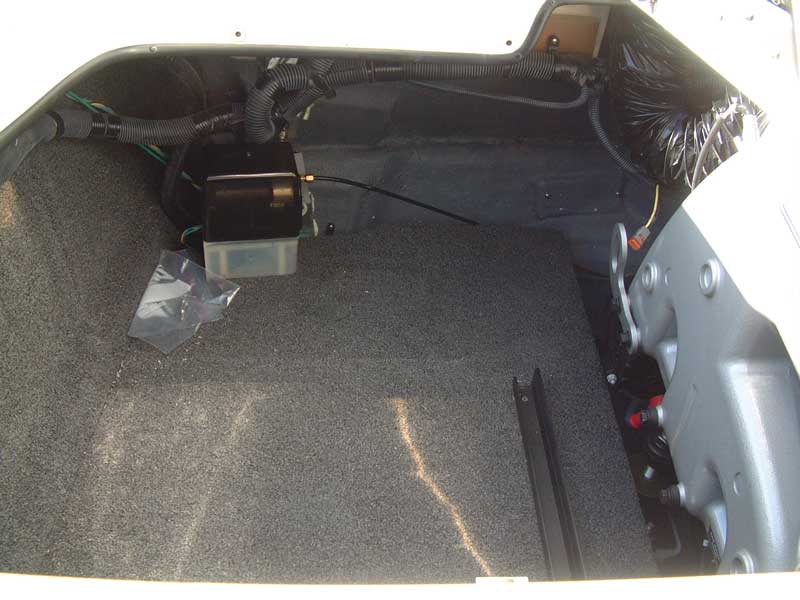
In this photo of the starboard locker, the TAPS pump's mounting bracket has been removed and set aside. The TAPS pump itself is just sitting on the locker floor. The black plastic channel to the right is where the large factory engine divider (i.e. locker side wall) rests when it is installed.
The floor is pretty large. In its standard configuration there is no way it would come out of the locker hatch in one piece. Indeed, with the engine in place I'm not certain it could come out even with all three hatches and their metal support brackets removed.
Fortunately, Tige comes through again for its customers. The floor is covered by one big piece of carpet, but the actual structural material is comprised of TWO pieces, side by side along the long axis of the hull. The outermost edge (and floor piece) just lays on top of an angle in the hull's inner surface. The innermost edge (and floor piece) is secured to the engine stringers shown in earlier photos with stainless steel screws, one of which can be seen in the above shot while it serves double duty securing the plastic channel.
Once the plastic channel screws have been removed, you must feel around in the carpet for the remaining screws (they disappear rather well into the nap of the carpet). When all of the screws have been removed, both sides of the floor can be lifted - with the carpet acting as a living hinge and permitting the floor piece to fold in half.
It is then a VERY tight fit, but possible, to angle and jockey and coerce and cajole the folded floor out through the locker hatch. No cutting, no hatch removal, no irreversible changes are required. And once it's out, here is what you see:
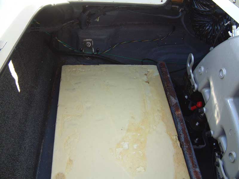
Despite its being visible in earlier photos, this is actually the first view of the top of the engine stringer that you see.
The big foam block under the floor takes the place of the factory hard ballast tanks when that option isn't ordered. I was really glad my boat came without the factory ballast, since that meant I didn't have to remove or work with/around them. (Side note: That "80 pound limit" for the locker floors doesn't apply when you have these foam inserts; that's only for when you have the factory hard tanks.)
Here is where I ran into my one irreversible step (other than cutting holes in the hull, of course): I could not figure out a way to get those foam blocks out. Perhaps Tige drops them in the hull before the attach the deck, or install the engine. I finally gave up and cut them in half with an old-fashioned hand wood saw since that would leave the narrowest cut, have the reach to go through the entire block, and do so while the block was still in the hull. The resulting two-piece block could still be reinstalled with no change in behavior or performance.
Once the block is out, we have arrived at our goal:
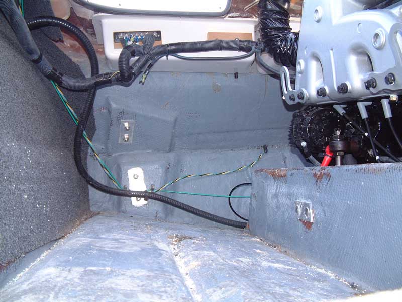
...a completely empty locker. In the left of this photo, you can see the "ridge" where one side of the locker floor used to rest. To the right is the engine stringer, on which the other side of the locker floor sat. Removing the floor and blocks has exposed things right down to the inner surface of the hull itself; the chines are even visible running along the longitudinal axis of the hull (lower left and center). Looking way, way up at the top of the photo, you can see the opening of the hatch. That vertical distance is amazingly tall, and now we can fill all of it with fat sac.
Likewise, the length of the locker space has been opened up all the way back to the transom. We've gained over a foot of length that was once wasted behind the locker walls on batteries and pumps. And it goes from the hull to the deck. AND it's the most valuable real estate on the whole boat from a ballasting perspective: As far back as possible, as deep as possible.
There's still a lot of rework and cleanup to prepare these spaces for ballast. That will be the topic of the next installment.
More soon... thanks!
Comment
-
Incorrect our floor is the same =) I did this at the begining of summer.. Just too lazy to snap and upload pics! I pulled the foam out my whole driver side and slid a bag down into it and fill it then put my 1500lbs bags ontop of that!Originally posted by duffymahoney View PostHow big are the custom sacs gonna be? You can't remove the floor on an older tige 24v correct?www.1320diesel.com Home of the Fastest Diesels!
http://youtu.be/dEDdM0Y3IGs?hd=1
Comment




Comment