Announcement

Collapse
No announcement yet.

Where do you put the intakes and pumps on a 24Ve?

Collapse
X
 
  • Filter
  • Time
  • Show
Clear All
new posts

    Where do you put the intakes and pumps on a 24Ve?

    I visited my 24Ve in storage today and spent some serious time planning for my ballast system. I'm a little baffled as to where most folks put their intakes and pumps.

    For many boats, I see lots of photos showing intakes and pumps being installed in front of the v-drive and behind the fuel tank. However, that space is rather small on my 24Ve - and it's not accessible without tools (a section of the seat must be removed) so accessing the shutoff valve(s) would not be quick in an emergency. I have a photo of this small space:


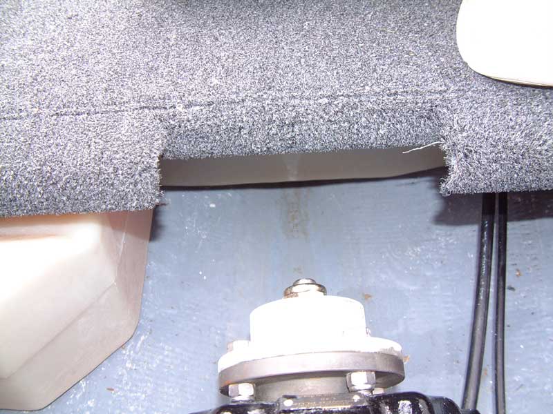
    Beside and behind the v-drive/transmission, I have the triducer on one side aft about a foot and the engine cooling water intake aft about a foot on the other, plus lots of hoses and other obstructions. No real room there, since I don't want to install intakes in front of either of those existing thru hulls.

    That leaves the area behind the engine ("bilge"). The rudder's cable and swing area take up the center. The muffler and exhaust take up the port side. That leaves the starboard side, an area very approximately 8-10 inches wide (between the keel and a large stringer) and perhaps a couple of feet long (from the transom extending toward and under the engine and transmission oil intercooler). This appears to be the only reasonable place that still might be accessible and won't interfere with existing fittings.

    Given this limitation, I'm tempted to go with a single large (~1.5 inch) intake and a manifold. There's great controversy surrounding manifold systems, and I'd go with separate intakes except that I'm not sure there's room for them. A single thru hull could turn a 90 through a single valve and then T to each of three pumps, taking up less overall surface area than if I used a separate thru hull, 90, and valve for each one.

    There may be space on either side below the battery platform, and the TAPS box platform, but I haven't yet tried to remove those and see what's under them. It may be structural foam since I don't have factory ballast.

    Where have others put their intakes and pumps on 24Ve's?
    Last edited by IDBoating; 01-18-2011, 04:50 AM.

    #2
    My pump intakes are just aft of the v drive near that transducer you talked about.

    Pm coming your way.
    Last edited by Ewok; 01-18-2011, 07:18 AM.
    2009 RZ2, PCM 343, MLA Surf Ballast, Premium Sound.
    2013 Toyota Sequoia 4WD W/Timbren SES

    Comment


      #3
      Originally posted by Ewok View Post
      My pump intakes are just aft of the v drive near that transducer you talked about.
      As I mentioned, I'm worried about turbulence near the triducer. I've installed depth sounder transducers on other boats and they can be VERY sensitive to turbulence caused by other thru hulls nearby, and especially toward the bow.

      Comment


        #4
        Like I mentioned, we've got a 24Ve coming in for a monster system in a couple of weeks, so I'll shoot some pictures for you of where we locate everything.

        You definitely want to stay downstream or to the side of the triducer, but that's really the constraint.

        Manifolds can work, especially for relatively low pressure aerator pumps, so we can definitely find a solution that will work for you, but what makes the most sense will ultimately depend on which aerator pumps you decide to go with.
        WakeMAKERS.com | WakePROPS.com

        Comment


          #5
          Originally posted by jason@wakemakers.com View Post
          Like I mentioned, we've got a 24Ve coming in for a monster system in a couple of weeks, so I'll shoot some pictures for you of where we locate everything.
          I'm 90% certain I'll be using that space opposite the muffler/exhaust behind and below the engine. It's the largest contiguous space I could find that is also reasonably accessible in an emergency.

          I think locating the thru hull nearest the transom, then working forward with the 90/valve/etc., will help insure that trapped air will tend to self-purge. The hull should always be lowest at the stern and rise toward the bow. Watch out for the Tige's ConvexV hull shape, though... the slope of the hull back there can be deceiving. For that reason I will probably try to put the thru hull down near the hull's centerline (keel) and after the 90 "tilt" the inlet pipe up along the hull's inside surface.

          Another possibility would be to skip the 90 and mount the valve directly to the thru hull, then the pump directly to the valve. This non-manifold approach would yield a tall arrangement with minimal footprint. There is definitely sufficient vertical space behind the engine to mount this way, but I am concerned that the pump may end up above the waterline. If T800's or 405FC's were used, the valve could be a 3/4 inch which would be quite a bit shorter than a 1.5 inch manifold-scale valve. But the pumps are ~6 inches tall all by themselves, with their outlets (and thus likely their impellers) roughly centered on that height. Let's presume the bottom four inches must be below the waterline to insure self-priming; add 3-4 inches for the valve and another inch or so for exposed threads and the waterline would have to be safely 10+ inches above the hull's inner surface. Looking at the distance from my swim platform (presumed to be the water's surface) to the keel, I'm not sure there's a reliable 10-12 inches there. But such a vertical arrangement is very tempting because it would dramatically simplify everything and permit a dedicated thru hull per pump.
          Last edited by IDBoating; 01-18-2011, 11:56 PM.

          Comment


            #6
            Just go look at how Tige is doing it from the factory and copy them.

            Comment


              #7
              Originally posted by Timmy! View Post
              Just go look at how Tige is doing it from the factory and copy them.
              That's what I thought too, until I saw how they do it!

              1) The photos I have from the Tige factory during a 24 foot hull outfitting show them not using valves at all (!!!). Their pumps screw directly into their thru hulls. No provision for closing off the hole(s) in the hull if something(s) goes wrong.

              2) They install them in front of the v-drive and behind the fuel tank. That area isn't accessible on my 24Ve without tool-assisted disassembly of the rear seat. Of course, I guess that doesn't matter much if there are no valves to close anyway {grin}.

              I wouldn't worry so much about valves - after all, the engine's cooling water intake doesn't have one - except for the pumps. The pumps have replacable motor cartridges. You're relying upon the effectiveness of the seal between the plastic pump body and its detachable plastic motor housing to keep water out of your boat. I want a valve there. (This contrasts with the engine's thru hull, which has a very stout 1.25 inch water line and stainless hose clamp. I'm not worried about that failing.)

              Comment


                #8
                WA,

                I will be in the shop late morning tomorrow. I will mock up a thru-hull, valve, pump and then a thru-hull, elbow, valve, pump. and get you some rough dimensions of space needed for each.
                Mikes Liquid Audio: Knowledge Experience Customer Service you can trust-KICKER WetSounds ACME props FlyHigh Custom Ballast Clarion LiquidLumens LEDs Roswell Wave Deflector And More

                Comment


                  #9
                  Originally posted by chpthril View Post
                  I will be in the shop late morning tomorrow. I will mock up a thru-hull, valve, pump and then a thru-hull, elbow, valve, pump. and get you some rough dimensions of space needed for each.
                  Thanks, that would be great! Please use the 405FC's as I believe that's the direction I'm going. Same 3/4 inch standard pipe fitting as the T800 but ostensibly more volume/minute.

                  Think a full 3/4 system on the intake is sufficient if it's a dedicated, straight, short feed to the pump's inlet? I would go one inch but I'm sure the valve would have a longer body and then an adapter would be needed, adding even more length. I'm thinking that even though it's 3/4 inch, a "full flow" valve and a very short distance from pump to hull will present very little restriction.

                  Once we have height measurements, I'll visit the 24Ve in storage again and try to gather "waterline relative to inner hull" data.

                  Thanks again!

                  Comment


                    #10
                    I dont know what pictures tige sent you but all of our boats have a ball valve before the pump on the through hull.
                    Also when we add a system if not so equiped we add a hatch just like they did on the 2010 under the seat which gives access to the pumps and center drain which add to every boat that goes on a lift.

                    Comment


                      #11
                      Originally posted by dom w. forte View Post
                      Also when we add a system if not so equiped we add a hatch just like they did on the 2010 under the seat which gives access to the pumps
                      I have a hatch like that under the seat CUSHION, yes. It's small, but I suppose I could reach my arm through up to the shoulder to reach something on the hull.

                      Comment


                        #12
                        Originally posted by WABoating View Post
                        I have a hatch like that under the seat CUSHION, yes. It's small, but I suppose I could reach my arm through up to the shoulder to reach something on the hull.
                        My thru hulls have a ball valve shutoff and I can reach them through the little cover under the seat cusion on the back bench.
                        2009 RZ2, PCM 343, MLA Surf Ballast, Premium Sound.
                        2013 Toyota Sequoia 4WD W/Timbren SES

                        Comment


                          #13
                          Tige has started installing ball valves on their ballast thru-hulls, albeit PVC ones, but something is better than nothing. Here's a picture I took of a 2011 RZ2 we had in recently, this was taken through the access panel under the rear seat.


                          Here are some dimensions for for the assemblies you're looking at (we'll have all of these dimensions for every product up on our site shortly):

                          3/4" Bronze Thru-hull -> 3/4" Bronze Ball Valve -> Rule 405FC
                          7.25" +/- .5" H x 2.76" W

                          3/4" Bronze Thru-hull -> 3/4" Bronze Street Elbow -> 3/4" Bronze Ball Valve -> Rule 405FC
                          4.5" +/- .5" H x 7.25" +/- .5" L

                          Either one will work in the boat with respect to the waterline, so it's just about finding what will fit best in the bilge compartment.
                          WakeMAKERS.com | WakePROPS.com

                          Comment


                            #14
                            Originally posted by jason@wakemakers.com View Post
                            "Tall" (without 90): 7.25" +/- .5" H x 2.76" W

                            "Short" (with 90): 4.5" +/- .5" H x 7.25" +/- .5" L

                            Either one will work in the boat with respect to the waterline, so it's just about finding what will fit best in the bilge compartment.
                            I presume the above height dimensions are overall height, i.e. to the top of the pumps? The impeller will be in the middle of the pump somewhere, and as long as the impeller is below the waterline the pump will be self-priming. Therefore, even with the "tall" configuration, as long as the inside surface of the hull is at least 7.25 inches below the waterline it should work.

                            I'm pretty certain there is at least that much draft back in the bilge area. I'll take some measurements next time I'm near the storage facility.

                            Another reason I like the vertical configuration: Strength. I'm concerned about the lever arm created by a pump hanging at the end of an elbow. Worse yet would be a manifold consisting of several pumps and hoses. That's potentially a lot of stress on the elbow and all intermediate fittings.

                            My online research suggests that a one inch ball valve adds about 0.5 inches in length (height) over a 0.75 inch ball valve. If the draft is available, do you think it wise to go to one inch on the inlet? The pump itself only uses a 3/4 inch inlet but it's never good to starve a pump for water. A 1.0 to 0.75 adapter would also be required on top of the valve, but those don't add much height since they end up concentric to the two items they are adapting.

                            Comment


                              #15
                              You will definitely have enough draft to keep the pump flooded either way you decide to go. Personally, I would skip the street elbow since you don't need it, you'll save money, and it's easier to ensure the pump body will always be purged in that configuration.

                              I wouldn't worry about the moment from one pump (they don't weigh that much, but if you were to go the manifold route and suspend the entire thing to one side (versus branching it off the thru-hull and ball valve from the middle) then you would definitely want to support it at the end.

                              There is no reason to use 1" hardware to feed an individual pump, supply is infinite (the lake), and the distance we're talking about between the hull and pump is so short that velocities won't be a problem, and there will be plenty of volume for the pump. In these situations we match the pump to the thru-hull based on ease of installation, which is what makes the 405 so attractive.
                              WakeMAKERS.com | WakePROPS.com

                              Comment

                              Working...
                              X